 Defining E-Mobility
Menu
One software-defined drive platform, from e-rickshaw to cargo three-wheeler.
Most drives are fixed at the factory. Ours keep the vehicle's behaviour in software, on hardware and firmware we design ourselves.
Connectivity and diagnostics
Diagnostics, analytics and over-the-air updates through the vehicle's connected cluster.
Motor and vehicle control
Motor control and vehicle control in one unit.
Power electronics
A high-efficiency inverter in four power stages.
See the controller at work on a vehicle.
Drive an e-scooter or a cargo three-wheeler through the Indian Driving Cycle, inject a fault and watch the response, and send an over-the-air update.
Try the vehicle simulator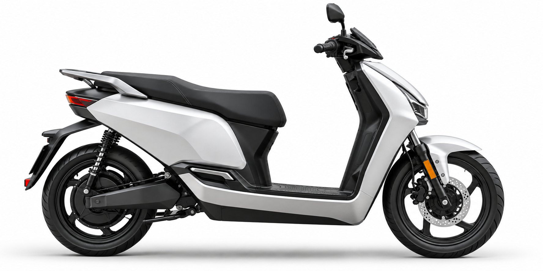
Fewer boxes on the vehicle.
A typical electric two- or three-wheeler carries a separate motor controller, vehicle control unit, DC/DC converter, on-board charger and body control module. We have combined the first two into one unit.
Five separate units
Motor controller, VCU, DC/DC, OBC and BCM, each with its own housing, wiring and supplier. Integration is complex and system cost is higher.
Motor controller and VCU in one
Motor control and vehicle control share one integrated controller, with fewer components, less wiring and simpler integration.
Built on our own hardware, firmware and algorithms.
Performance
- Field-oriented control
- Adaptive regenerative braking
- Up to ~97% controller efficiency
Functional safety
- ASIL A and ASIL B compliant hardware
- Patented fault-detection logic
- Limp-home capability
Full-stack IP
- Hardware and firmware
- Vehicle and motor control algorithms
- 2 granted Indian patents
Built for India
- Optimised for Indian drive cycles
- Rated for heat, dust and vibration
- Engineered and supported locally
Where the platform goes next.
- TODAY
Motor controller + VCU
One integrated controller, in production.
- NEXT
More of the vehicle's electronics
We are extending the platform to integrate more of the vehicle's electronics. Talk to us about what is coming.
A rare-earth-free EESM powertrain.
An electrically excited synchronous motor uses a wound rotor in place of permanent magnets. The rotor field becomes something the controller sets, and rare-earth magnets leave the bill of materials.
We are designing the motor and its controller as one system and validating them together for light commercial vehicles. The work is supported by an ARAI technology grant.
From your requirement to stable production, in five gated phases.
Every programme follows APQP, the automotive industry's quality-planning framework. Product and production line are developed together, and each phase closes at a gate before the next begins.
-
PHASE 1
Plan and define
Your requirement becomes design goals, reliability targets and a programme timeline.
Gate: feasibility agreed -
PHASE 2
Product design
Hardware, firmware and mechanicals are designed together, with design FMEA, safety analysis and a design verification plan (DVP) agreed with you.
Gate: design freeze -
PHASE 3
Process design
The production line is planned alongside the design: process FMEA, control plan and end-of-line test.
Gate: line ready -
PHASE 4
Validation
Every test in the DVP is run and reported (DVP&R), then a production trial run at rate.
Gate: PPAP approval -
PHASE 5
Launch and feedback
Start of production with extra early checks, then field and line data fed back into the design.
Gate: stable production
Want to go deeper?
Our application engineers can walk your team through the architecture and interfaces.